Drawing Phylogenetic Trees, Connor Style
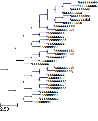
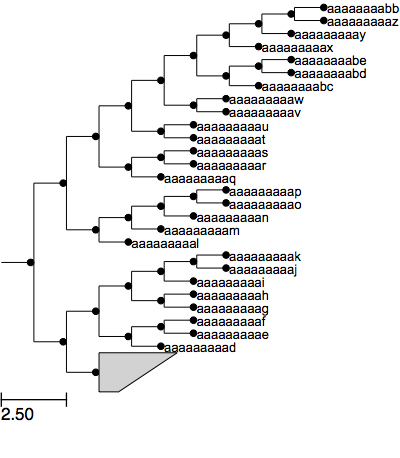
I do a lot of work in phylogenetics, which means that for just about every paper I’ve written I’ve had at least one figure that is a phylogenetic tree. Making pretty looking trees for a publication is tedious and my previous workflow involved using ARB for actually drawing the tree and producing an initial file in postscript, and then loading that into Adobe Illustrator to make everything beautiful. The problem with this is that it is not an automated process so any time I need to change the tree I need to redo all of the ‘beautifying’ manually. Recently I coded up an alternative approach using the excellent ete package for python to draw trees exactly how I want. One of the nicest things about drawing trees in ARB is that you can collapse clades into wedges. Unfortunately, while ete does allow you to collapse clades it doesn’t provide a way to show the collapsed node as a wedge, the only options are a square or a circle. But there is the option to create a custom face which is exactly what I did. Below is a function to create ARB-style wedges:
 def polygon_name_face(node, width, height, width_percent):
    """create a wedge shaped face in the style of ARB

        Args:
            width (int): size in pixels for the width of the wedge
            height (int): size in pixels for the height of the wedge
            width_percent (float): change the angle of the point of the wedge. This must be a number between 0 and 1

        Returns: QGraphicsRectItem: The Qt graphics item of the polygon
    """
    points = [ (0.0, 0.0), # top left point
               (width, 0.0), # top right point
               (width * width_percent, height), # bottom right point
               (0.0, height), # bottom left point
               (0.0, 0.0) # back to the beginning
             ]
    shape = QPolygonF()
    for i in points:
        shape << QtCore.QPointF(*i)
        ## Creates a main master Item that will contain all other elements
        ## Items can be standard QGraphicsItem
        masterItem = QGraphicsRectItem(0, 0, width, height)
        # Keep a link within the item to access node info
        masterItem.node = node
        # I dont want a border around the masterItem
        masterItem.setPen(QPen(QtCore.Qt.NoPen))
        polygon = QGraphicsPolygonItem(shape, masterItem)
        # Make the wedge grey in color
        polygon.setBrush(QBrush(QColor( '#D3D3D3')))
        # Print the name of the node
        text = QGraphicsSimpleTextItem(node.name)
        text.setParentItem(polygon)
        # Center text according to masterItem size
        tw = text.boundingRect().width()
        th = text.boundingRect().height()
        center = masterItem.boundingRect().center()
        text.setPos(center.x() + tw/2, center.y() - th/2)
        polygon.setPos(0, masterItem.boundingRect().y()/1.5)
        return masterItem
And then to actually use it in a script, set up the tree style. I like to mark internal nodes with bootstrap support >70% with a grey circle and >90% with a black circle as well. Below is the function that I use to add in the groups.
 def master_ly(node):
    style = NodeStyle()
    style['shape'] = 'circle'
    if node.support >= .90:
        style['size'] = 5
        style['fgcolor'] = 'black'
    elif node.support >= .70:
        style['size'] = 5
        style['fgcolor'] = 'grey'
    else:
        style['size'] = 0

    if node in grouping_nodes:
        style['draw_descendants'] = False
        # Create an ItemFAce. First argument must be the pointer to
        # the constructor function that returns a QGraphicsItem. It
        # will be used to draw the Face. Next arguments are arbitrary,
        # and they will be forwarded to the constructor Face function.
        # in this case we pass through the width, height, and width_percent for
        # the wedge.
        F = faces.DynamicItemFace(polygon_name_face, 60, 30, 0.25)
        faces.add_face_to_node(F, node, 0)
        node.set_style(style)
Finally putting it all together
from ete3 import Tree, faces, NodeStyle, TreeStyle
# We will need to create Qt4 items for making our custom polygon
from PyQt4 import QtCore from PyQt4.QtGui
import QGraphicsRectItem, QGraphicsSimpleTextItem, \
       QGraphicsPolygonItem, QPolygonF, QColor, QPen, QBrush
# Populate this list with the root node of a clade
# that should be turned into a wedge
grouping_nodes = []
# load in your tree from somewhere, this is for fake data
t = Tree() t.populate(30) ancestor = t.get_common_ancestor("aaaaaaaaa", "aaaaaaaaac")
grouping_nodes.append(ancestor)
ts = TreeStyle()
ts.layout_fn = master_ly
# order the subtrees in ascending order
t.ladderize(1)
t.show(tree_style=ts)
There are improvements to be made with the way I’m drawing the wedge. First, there isn’t any border between the top of the wedge and the next leaf — you can see the name “aaaaaaaaad” is a bit cramped. Second, ARB has a nice feature which changes the wedge dimensions based on the number of grouped leaves which I haven’t yet implemented.